7-button zigbee wall controller - III
Click to view video
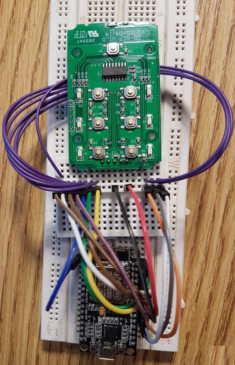
Here it is, the first attempt at a replacement module. All 7 leds are controllable, and all 7 push buttons work as intended.
Luck or good planning? I used up all the pins with no need to re-wire. If you know the esp8266 well, you will know there is a limited amount of gpio and even less of them can be shared/used flexibly as they are shared with other functions such as GPIO-0 to select boot mode.
The replacement module is going to be an ESP12 or ESP07 depending on signal integrity.
Eventually a PCB duaghter board will be made so that it can be a simple swap of the ORVIBO module.
For prototyping I used a nodemcu board as its the simplest to do trials on.
Some things to consider when planning the replacement module:
- The push buttons on the mcu board are all pulled high
- There is capacitors on the push buttons to do some hardware debouncing
- The led's are driven by the HC595
- The push buttons are directly connected to the module
- The led's use up bits 1-7 of the HC595, 0th is left unused.
- The leds are pulled low to turn on.
- Voltage is 3.3v
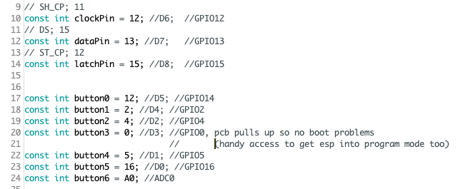
Pin planning process
- Use up any pins that can be pulled high at boot to connect to the push buttons
- Next place the HC595 lines, for our purpose we only need 3 outputs - clk, data, latch. Due to the low speed, we can bit-bang the output, no need to use hardware SPI.
During the 2nd step, I needed 1 more output pin but there was none I could easily use. I moved one of the push buttons to ADC0.
Using ADC0 as a digital i/o is as simple as assigning a threshold to consider a 0 below, and 1 above. It was as simple as using 500 (1024/2 = 512).
Now I had the extra pin I needed for the HC595.
The results:
Success! See video up top.
The 7-button controller is working, all buttons are detected and acted upon, with the LED's reacting as well.
Code/Program
For the proof of concept, I simply made the leds toggle state one by one. Pushing a button would toggle that led.
Grab the POC Code here: esp8266-wall-switch-test1.ino
Whats next?
- Integrate the ESP12 into the back of the ZB-SC7
- Expand the proof of concept code into proper wifi-manager/ota/mqtt code.
- Design PCB daughter/module board