Arduino DCC Monitor
In starting to build the custom dcc decoders for my layout I found some issues with JMRI (DecoderPro) and the decoder not behaving as expected.
After some back and forth between code and investigating the library I decided to try to simply listen for the dcc packets to see what was really happening.
This is where the dcc monitor sketch was born.
The sketch uses the NmraDCC library to listen to the DCC signals on an Arduino Pro Mini 5v 16mhz.
It is based on the sample sketches and some functionality was inspired by the work of Geoff Bunza in his updates to the library and his 17 function DCC Decoder samples.
Changes from NmraDCC sample
I have made the following changes/improvements to better suit my needs and compatibility with some of the other decoders Im working with.
// - Factory default's CV's on writing to CV8. Implemented Geoff Bunza's auto-reset on every load concept in a different way.
// - Added ability to detect if eeprom is blank on load (check for 0xFF in a specific location) and reset CV's if needed
// - Added default CV29 value to FactoryDefaultCVs array for when eeprom is blank the library doesnt base its CV29 changes on 0xFF
// - Resets arduino on CV factory default
// - Made ACK pin into define for easy enable/disable during compile
// - Handle JMRI ACC State data in notifyDccAccState(). Account for the slight difference in JMRI data as seen in my experiments.
The last point is the most important reason this code exists. I had trouble with the notifyDccAccState() function.
During my trials I found that DecoderPro was sending the state differently than the sample code expected.
JMRI puts out the accessory state in the last bit of the "OutputAddr" versus in the 3rd bit as the library expects the "state".
As well the library (or JMRI) was putting out the OutputAddr relative to the bit position: 1,3,7,etc which while correct was not as visually simple to discern so I added some code to shift over the bits so that the final result would be 0,1,2,3
  //shift over the bits so the outputaddr is 0 to 3
   uint8_t OutputNum = OutputAddr >> 1;

   //JMRI puts out the state as the right most bit of pDccMsg->Data[1], the state argument doesnt change in JMRI Turnout.
   uint8_t StateProper = OutputAddr & 0b00000001;
Code
You can download the sketch here: Decoder_Basic_Monitor_v1.ino
Program the code to your arduino then launch the Tools->Serial Monitor (make sure its set to 115200 baud) and watch the debug lines.
Try sending dcc commands from your throttle and watch them on the serial terminal live.
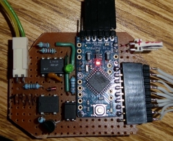
Circuit
Follow the circuit here http://mrrwa.org/dcc-decoder-interface/
The bottom half is the "listening" circuit, while the top half is the optional "ACK" circuit.
Alternatively you can follow Geof's circuit from here http://model-railroad-hobbyist.com/node/19446 ( direct link to circuit ) for seperate power supply method, or follow this one http://model-railroad-hobbyist.com/node/19070 for a circuit that can use electricity from the track.
I have used both of his circuits, but for arduino testing with debugging to the PC the 1st (seperate power supply) circuit is easier as the pc will provide the power to the arduino.
Details
Note that on every reset the CV's will get set back to defaults unless you uncomment the DECODER_DONT_DEFAULT_CV_ON_POWERUP define near the top of the code.
The code implements the following functions of the library
- notifyCVResetFactoryDefault() - will reset cv's to default + reset arduino
- notifyCVChange()
- notifyDccAccState()
- notifyDccSigState()
- notifyDccMsg() - raw logging of all messages
- notifyDccSpeed() - must not be in accessory decoder mode for this function to be called/logged
- notifyCVRead() - commented out, but shows when a CV is being read by the library or externaly (via dcc)