Capacitor Discharge Unit
In my layout I will be making use of some old Atlas turnouts (1970-80s) that are driven by two solenoids.
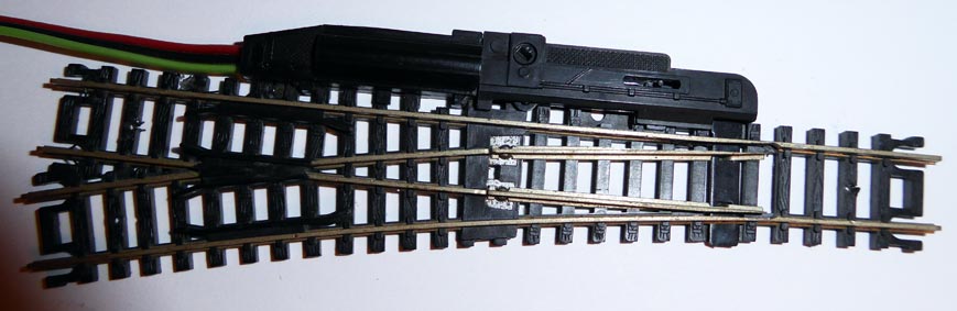
To drive these turnouts a momentary pulse of AC or DC in the range of 16-20v is needed.
Due to their nature of being solenoids they do require quite a bit of surge current, but for a brief period of time (50-200ms).
One problem that arises is that driving the solenoid for longer than this time can cause it to burn out, caution must be taken to not apply power for very long.
The other problem is the wear on the power supply every time the turnout position is changed. The surge of current can cause other electronics to momentarily loose power and in some cases trigger a false short circuit detector.
The solution to these problems is a Capacitor Discharge Unit.
Essentially a small circuit that holds a charge while the load is not being driven and then releases the charge in a quick blast when the turnout is driven to change. The added bonus is that if the turnout where to be left "on" the CDU limits the current passing thru to a mere 50ma (from the circuit designer) which is not enough to burn out the solenoid.
Plenty of information on CDU's can be found here http://home.cogeco.ca/~rpaisley4/CDPSU.html
The Build
The circuit I will be using can be found here http://www.talkingelectronics.com/projects/CDU-2/CDU-2.html "Capacitor Discharge Unit Mk II"
It is a simple yet effective circuit to build.
Note: Instead of a BD679 I used a MJE3055T transistor (as is used in the first link's circuits). It works fine for me.
Parts List
- 1 - MJE3055T (or BD679) transistor
- 4 - 2.2k 1/4watt resistors
- 1 - 1k 1/4 watt resistor
- 3 - 1N4004 diodes (1N4005, 1N4006, 1N4007 can be used instead)
- 1 - LED
- 1 - 2200uf 25v (or higher) Tantalum capacitor
or
2 - 1000uf 25v (or higher) Tantalum capacitor - Stripboard (veroboard, protoboard) 15 columns x 8 rows or bigger
- 2 - 2pin male connectors (optional)
Instructions
I used a single 2200uf capacitor to reduce space and simplify the build.
The parts were laid out to minimize the stripboard space used and elevate the tab of the transistor to allow for some passive air cooling.
First remove the copper rows/columns of the board that wont be connected. A dremel works great, but an exacto with patience also works.
I recommend placing the components in the following order
- resistors and diodes
- transistor and capacitor
- the led
- hookup wire or connectors
Once components are in place, make the bridges between the different rows on the underside.
Double check the rows on the circuit board are not bridged each other where they shouldnt, it does happen and even a tiny bridge (short circuit) can be damaging.
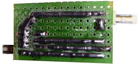
Stripboard Circuit
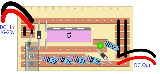
This is a top view of the circuit, remmember when working on the underside to reverse your work (like a miror).
The copper is on the underside !
Completed Unit